Description
The laser unit contains two sensors, a laser distance meter measuring the distance from the laser down to the road surface and a 3-axis gyro and accelerometer (IMU) used for measuring the movement of the laser unit itself.
When the car is moving and measuring, data is collected from the laser units and stored by the PC. When the measurement is complete, the stored data is analysed and the longitudinal profile, IRI and other parameters are created, one for each laser unit.
Multiple laser units may be used to measure multi-track parameters.
The ViaIRI consists of the following parts:
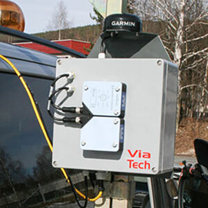
- One or more laser units with IMU placed on the front bumper or towing hook of the car
- Odometer
- GPS
- An interface box placed inside the car in order to collect odometer signal and to distribute power and Local Area Network.
- A windows PC used for data collection and data presentation.
Calculations
The measurement and calculations conform with ASTM E950, ASTM E1845 and World Bank Technical Paper 46 Class 1.
In addition ViaIRI supports Boeing Bump Index (FAA AC5380-9) and Ride Number (ASTM E1489)
Software
The ViaIRI user interface is based on the following:
- Touch screen ready. The operator can start and end measurements using touch screen interface.
- Easy to operate. Large fonts and few numbers make it easy for the operator to observe the measurements when the measurements are being performed.
- Background verification of measured data. The user interface checks the data from the sensor unit ensuring that the stored data is valid.
- The user interface may also show live IRI and MPD if the IRI and/or MPD options are selected. Notice that the live data only will give an indication of the value, as they may differ slightly from the data calculated after the measurement. This is due to improved filtering when the measurement is completed.
All the sensor data is saved in an internal database. The report generator produces reports in .csv or .xml format, which can be easily loaded into Microsoft Excel for further analysis. The reports may also be provided in a custom format. The report contains information about the date the measurement is performed, location, system name etc. Lastly, there is a list of rows containing calculated values for a given distance.
The Analyzer shown to the right may be used to give a graphical presentation of the test results. This program makes it easy to analyse one measurement, or compare several measurements. The image shows three different measurements of longitudinal profile for the same road segment.
Using ViaPPS Analyzer with ViaIRI measurements.
Technical specifications
| General, sensor unit | |
|---|---|
| Operating temperature | -10° to 60° C |
| Storage temperature | -20° to 70° C |
| Relative humidity | 5-95% non-condensing |
| Power requirement | 12V, 20W |
| Laser | |
| Laser type | Riftek RF607 |
| Laser power | < 80mW max |
| Laser class | 3B |
| Laser wavelength | 660 nm, (visible red) |
| Safety distance | 5.6 m |
| Measurement range | 250 mm |
| Measurement resolution | 0.025 mm |
| Maximum data rate | 70 KHz |
| Gyro | |
| Accelerometer resolution | 1.9 µg |
| Gyro resolution | 0.22°/hour |
| Data collection | |
| Laser sample rate | 70 KHz |
| Accelerometer sample rate | 2000 Hz |
| Gyro sample rate | 262 Hz |
| Odometer sample rate | 50 Hz |
| Measuring vehicle speed range | 20 – 120 kph |


